INSTRUCTION MANUAL

Introduction
The Claren Universal Folders have been designed to satisfy the following objectives:
Reduce format change time
Format change times are reduce by the reduction in the number of adjustments needed and also by the fact that the same parts are used for all format.
Improve the repeatability of format changes
Repeatability is improve by reducing the number of adjustments and therefore the possibility of mistakes.
Reduce the cost of new formats
Since the same folding parts are used for all formats adding a new format requires only new elevator plates and if not already available, a new product stop plate.
Improve the quality of the final product
The primary advantage of the universal folders is the change to the reverse or fold down sequence. Pushing the top panel down as the first step has inherent advantages when compared to using horizontal lifting venturies. Also the problem of the poor fold geometry on cube shaped packages is avoided with the fold down sequence.
General Part Names and Functions
Upper Fanning Air Jets and Folding Plates
In the first step of the process the upper fold is created by two folding plates which are attached to two existing upper contrast rails. On each side above these folding plates there are two fanning air jets which direct a curtains of air across the left and right vertical faces of the package to hold down the top panel while the tucks are performed. The air jets are supplied by the existing valves and timing of the “Flaps Blow”. Ball valves are included to disable the 2nd air jet on each side when not needed.
Full Height Ribbed Head Folders
The full height ribbed head folders replace all the existing single and double layer head folders and are used for all formats. Included with the head folders are also extension fingers which can be used to help break in the lower part of the tucked panel to improve the quality when needed. The milled ribs in the internal faces help to reduce the drag between the head folders and the poly thus reducing the occurrence of “dog ears”. The aluminum is GHA anodized to enhance the wear resistance.
Full Height Ribbed Counterfolders with Pitch Adjustment
The full height ribbed counterfolders replace all the existing single and double layer counterfolders and include also the pitch change courtesy of a spring loaded pin and linear rail. The existing left and right jam safeties are maintained. The counterfolders have the same ribbing as the head folders for reduced drag. The extended sheet metal plates are nickel/Teflon (tradename Cheniflon) coated after a bead-blast treatment to give the surface the appropriate texture. The aluminum is GHA anodized to enhance the wear resistance.
Lower Panel Fold Straightening Blowers
Added to the left and right counter folders are two air tubes. These air tubes and be used to correct defects in the lower panels before they are folded up by the low angle helices. They are most often used on double layer packages of large diameter rolls. The existing valves and timing of the “Subbase Blow” are used to supply these air tubes. They are adjustable in timing, longitudinal position, angle and flow volume.
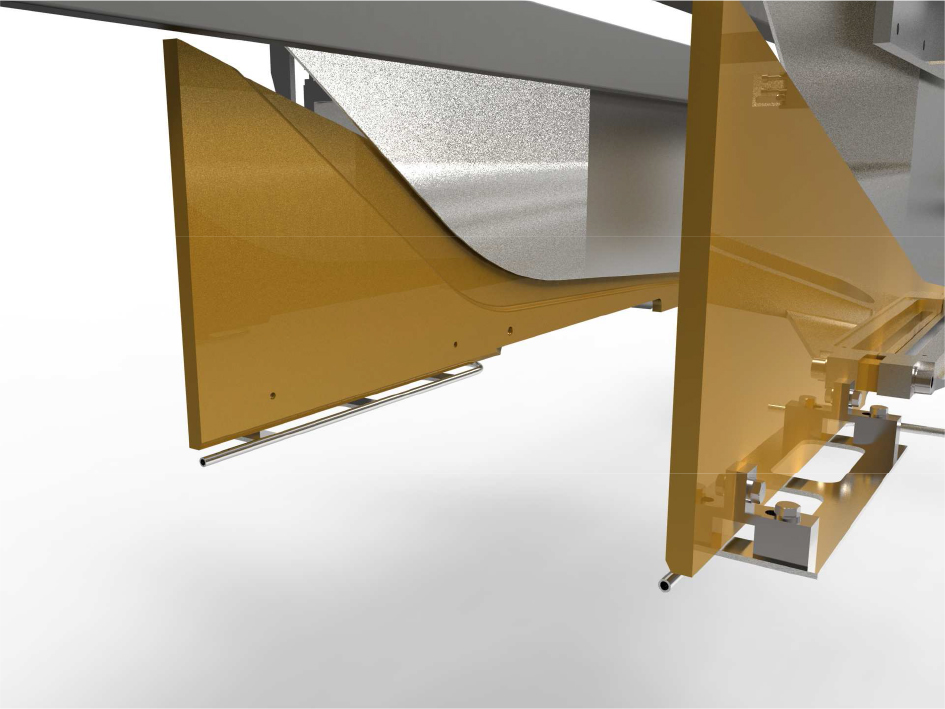
Nickel-Teflon (Cheniflon) Folding Panels
The old upper folding helices are replaced with nickel-Teflon (tradename Cheniflon) treated steel panels. The steel panels protect the upper and tucked folds during transport over the lower sealer. Their position inside the lower folding helices create a nip that helps to pull upward to create a tighter wrap. Prior to the surface treatment the steel panels are cleaned by glass micro-beading to create the proper surface texture that allows the wrapping material to slide freely.
Low Angle Lower Folding Helices
The existing lower folding helices that fold both the lower and upper panels of the package are replaced with folding helices that have a much more gradual folding angle. The more gradual angle is possible because only the lower panel is to be folded, the upper panel has already been folded down as the first step of the folding cycle. The lower angle helps to reduce trailing fold defect that are often present on packages of large diameter rolls. Both are manufactured from the same aircraft grade aluminum as the head and counter folders and have the same GHA anodized surface treatment.
Final Vertical Assist Blowers
Under the lower helices and before the sealing belts are installed two vertical blowing air tubes. These tubes blow in the area inside the lower helices between the package and helices. In the area of the lower sealer are installed some small plates to close the helix panel outside the area where the lower sealing is performed. These plates when positioned incorrectly cause damage to the lower sealer. These plates are often missing or damaged which allows a defect to form on the lower edges of the package. During the installation of the universal folders any of these plates remaining in the machine are removed and the associated defects are corrected with these blowers.
Installation and Fixed Dimensions
Machine Preparation
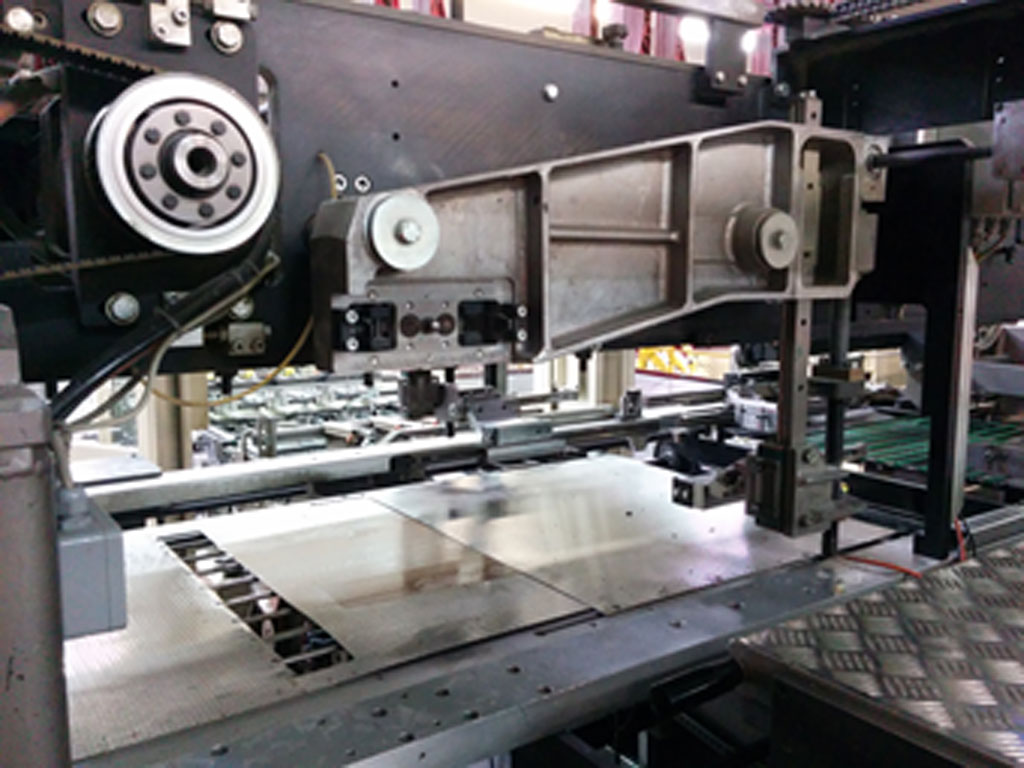
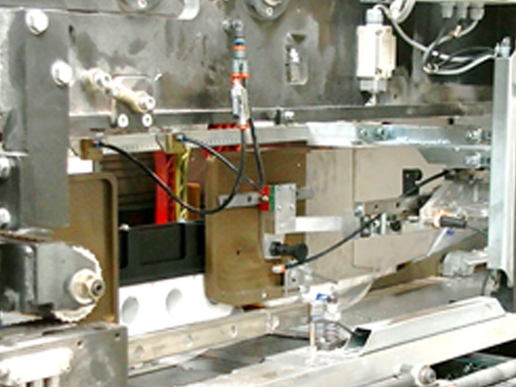
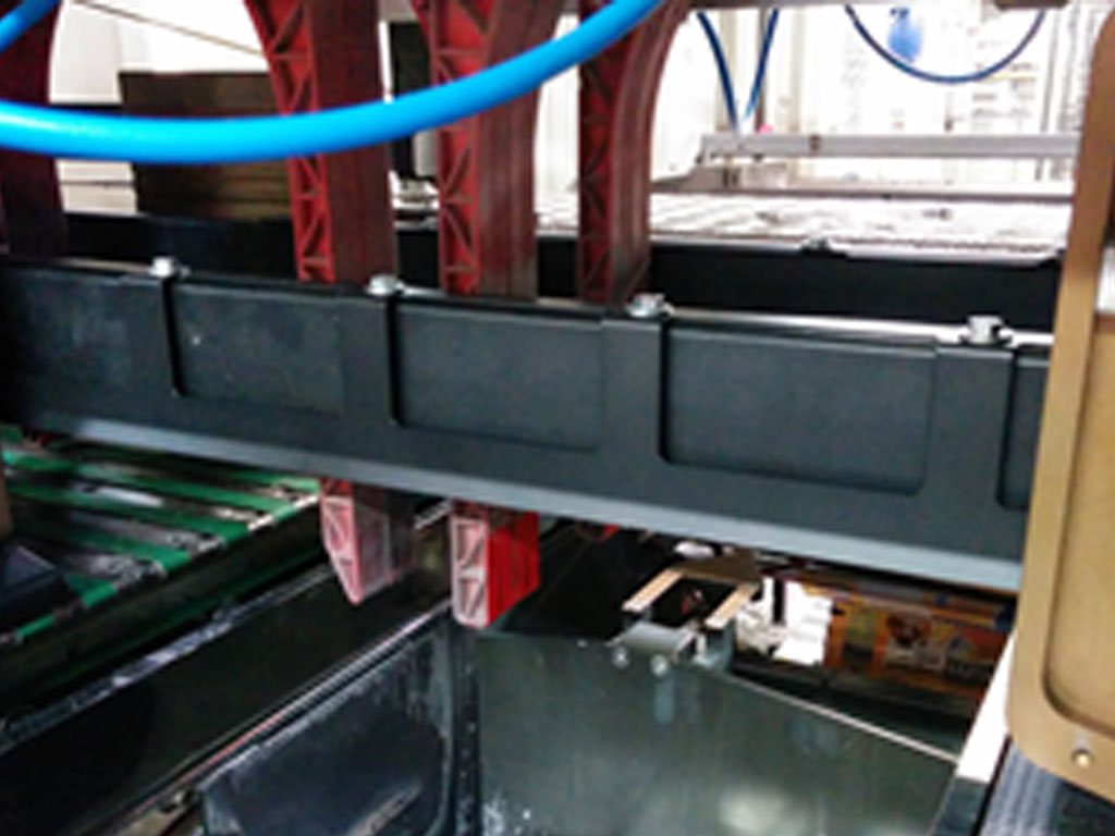
The machine is prepared for the installation of the new folders by emptying the upper body of the machine as indicated in the following photo example:
Disabling of counterfolder and venturi bars vertical movement
The parts are used for all formats and the necessary adjustments are reduced to a minimum, therefore the vertical movement of the counterfolders and venturi bars are no longer needed. The new counterfolders and vertical air jets will be installed at a fixed heights. The movements are disabled by shorting the chain that drives theirs’ and that of the upper contrast rails.

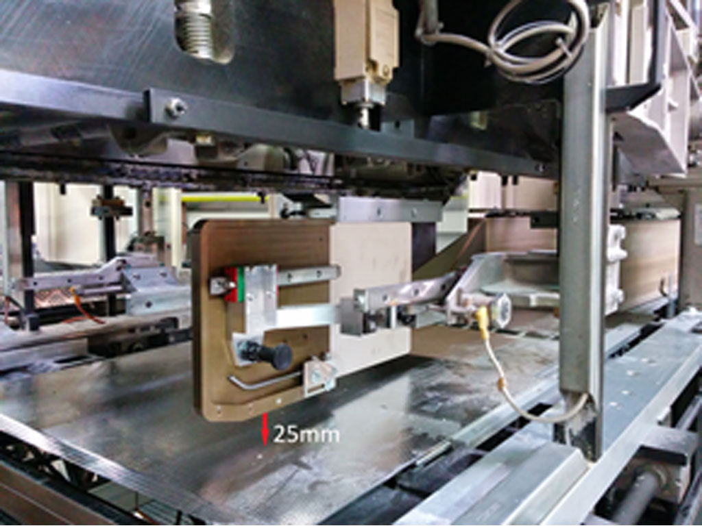
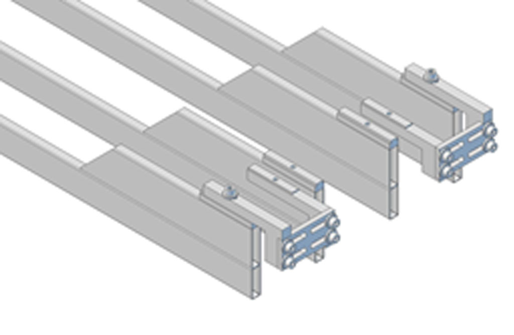
Counterfolder Installation and Positioning
The new counterfolders with extension plates and the fold straightening blowers are installed on the existing counterfolder supports
The vertical height of the counterfolders is set at 25mm from the deck to the bottom of the counterfolder.
The fold straigtening blowers are angled downward towards the deck. Both blowers are connected together with a y connector to one of the flow controls of the existing subbase blowers. The second subbase flow control is closed completely, it is not needed anymore.

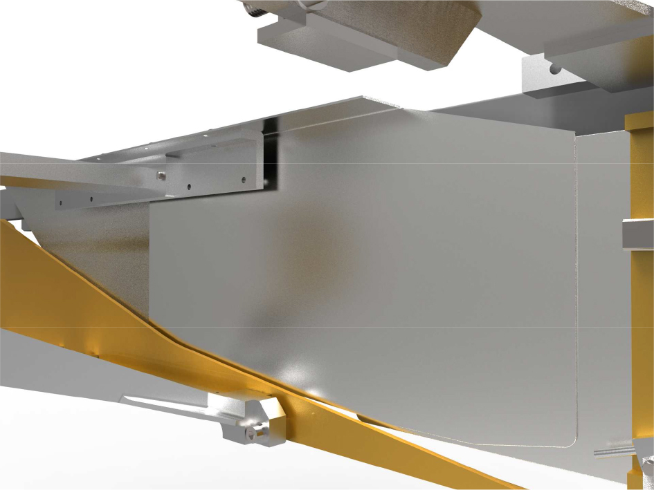
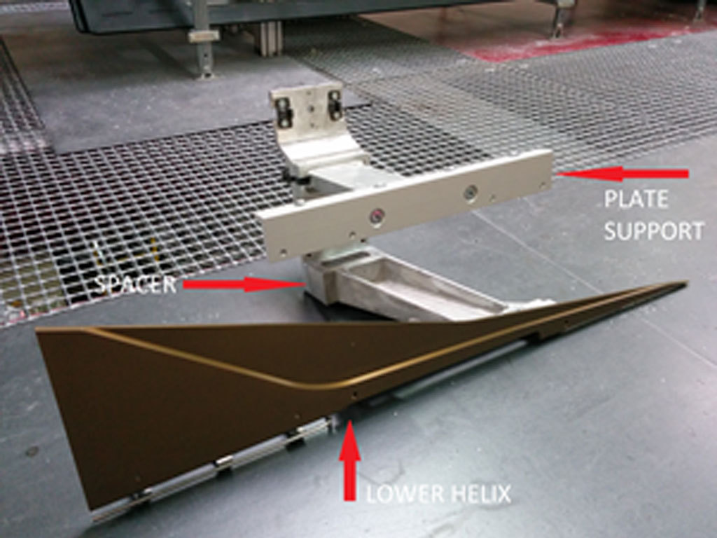
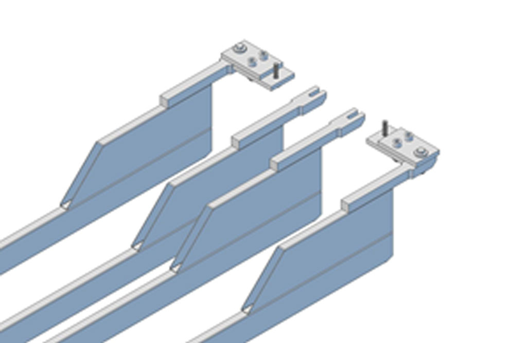
Lower Helix and Fold Panel Installation
The lower helices and folding panels are installed on the existing helix supports. Prior to insertion in the machine the supports are prepared with a spacer, the angled support for the folding panel and the lower helix with final blower.
This group is inserted in the machine without the folding panel.
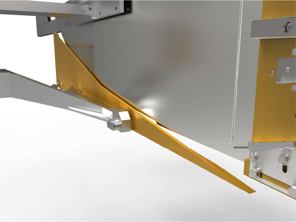
The folding panel is installed after taking care that the folding panel face is on the outside of the counterfolder extension plate.
The initial gap between the lower helix and folding panel should be set at approximately 4mm using the slots at the top of the folding panel. After that initial gap has been set then the 4 push screws are used to open the gap to 5mm and then the push screws are locked in position with the nuts. The combination of forces between fixing the upper position in the slots and then forcing the screws against the plate renders the panel more rigidly stable.

The final vertical assist blowers are connected together with a y-connector under folders and behind the lower sealer tower. The supply for these blowers is taken from the main machine supply after the safety valve. The flow is adjusted with a pressure regulator.
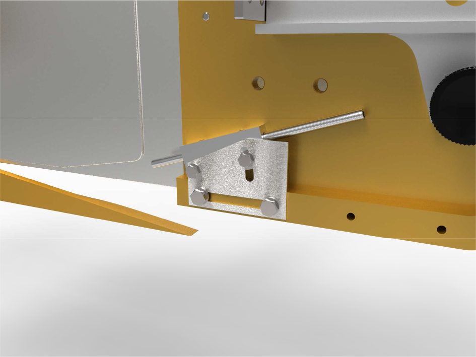
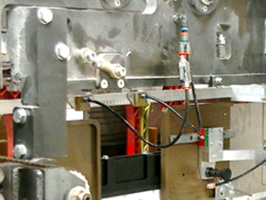
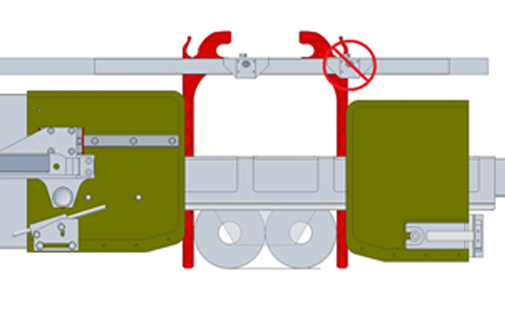
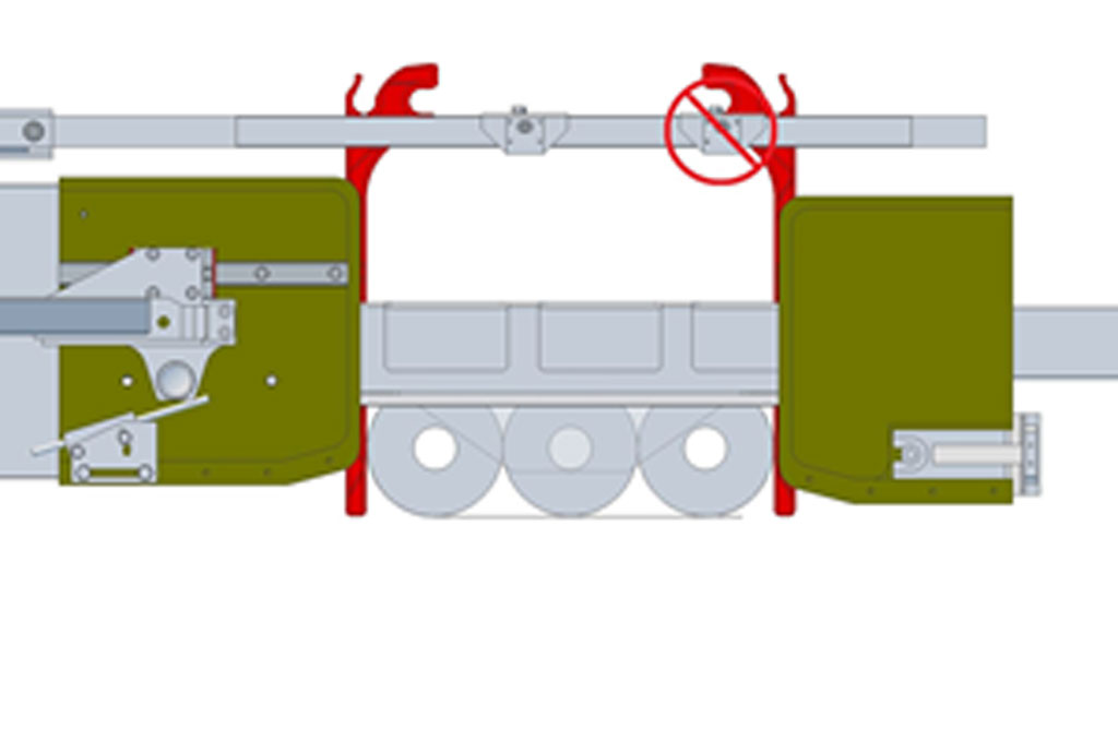
The upper air jet assemblies are mounted to the linear bearing that one supported the venturi bars. The vertical position is the distance of 4mm between the top of the counterfolder and the bottom of the spacer block of the support rail.
The horizontal position of the air jets is with the internal face of the support rail in line with the internal face of the counterfolder. This position will allow the contrast rail to pass the support bar when the height is adjusted during a format change.
The two air jets are connected the exising venturi air supply via a y-connector. As is indicated in the photo, the air jet closest to the head folder has a manual valve installed to disable the air jet when not needed.
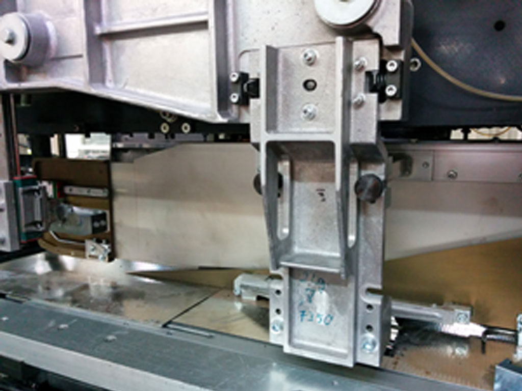
Head Folder Installation and Position
The head folders are installed on the existing single layer head folder supports. If the machine had previously the single and double layer adjustable format parts then the single layer supports will be included in the kit from Claren. If not using the additional finger, the head folder is positioned 10mm above the lower folder

Alternatively, if the extension fingers are to be used with the head folders then the height of the head folders will be adjusted to match that of the counterfolders.
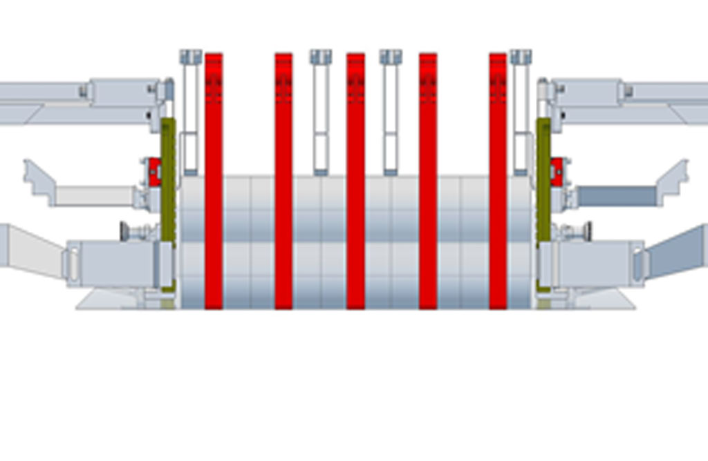
Upper Contrast Rail and Folding Bar Preparation and Installation
Two upper contrast rails are prepared with 6mm threaded inserts.

The folding plates are installed after the two contrast rails are installed in the machine.
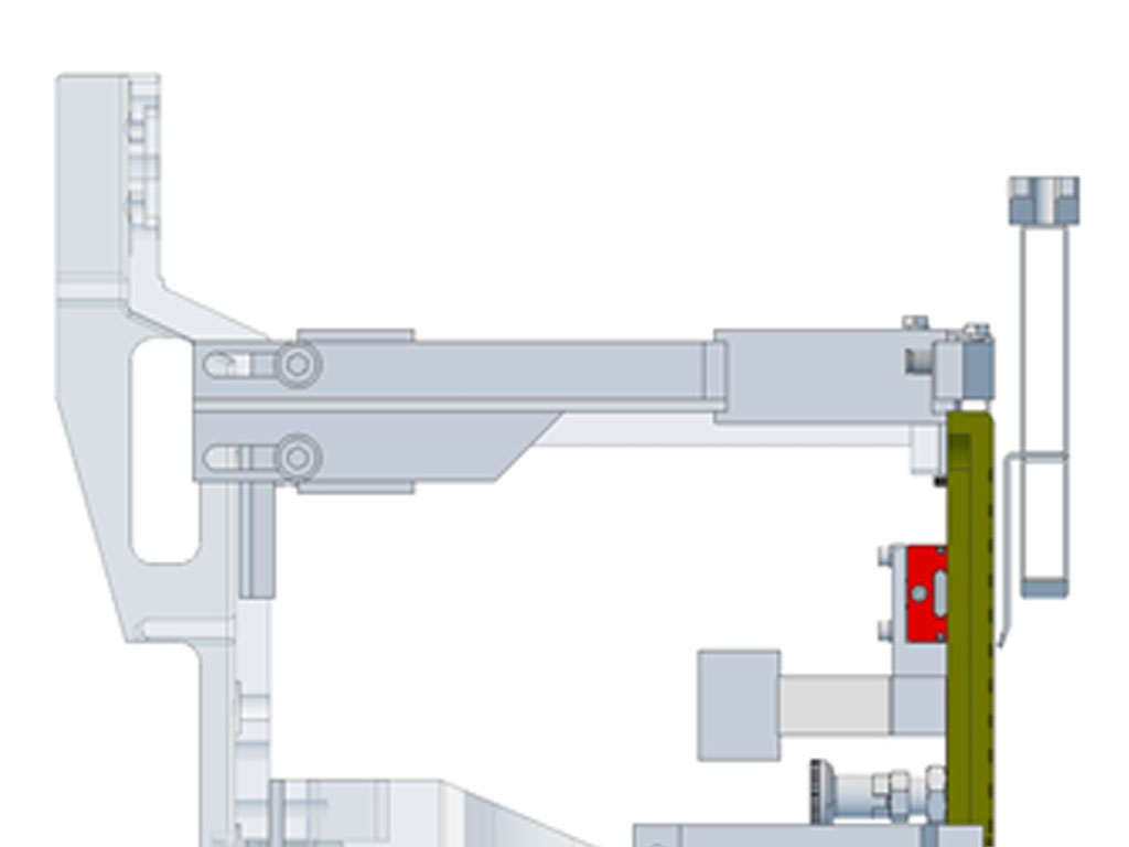
The positions of the contrast bars with the folding rails are dependent on the format as in this example rendering.
Format Change
Overview
The format change remains the same for the following machine sections:
Infeed Conveyor, Launchers, Single Bar chain, Infeed Stacker, Double Bar Chain, Elevator and Side Plates, Lower Sealer, Sealing Belts and Knife and Poly Section
The follow are affected by the Universal Folder retrofit:
Folding Section, Upper Contrast Bars and Overhead Finger Position
Process
The format change of the infeed, poly and lower machine body should be performed first so that the package can be centered in the machine. The height from the lower folder plate to the bottom of the contrast rails should be set to the height of the finished package (roll diameter x number of layers).
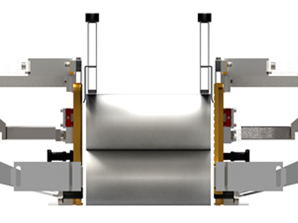
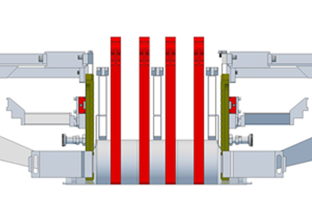
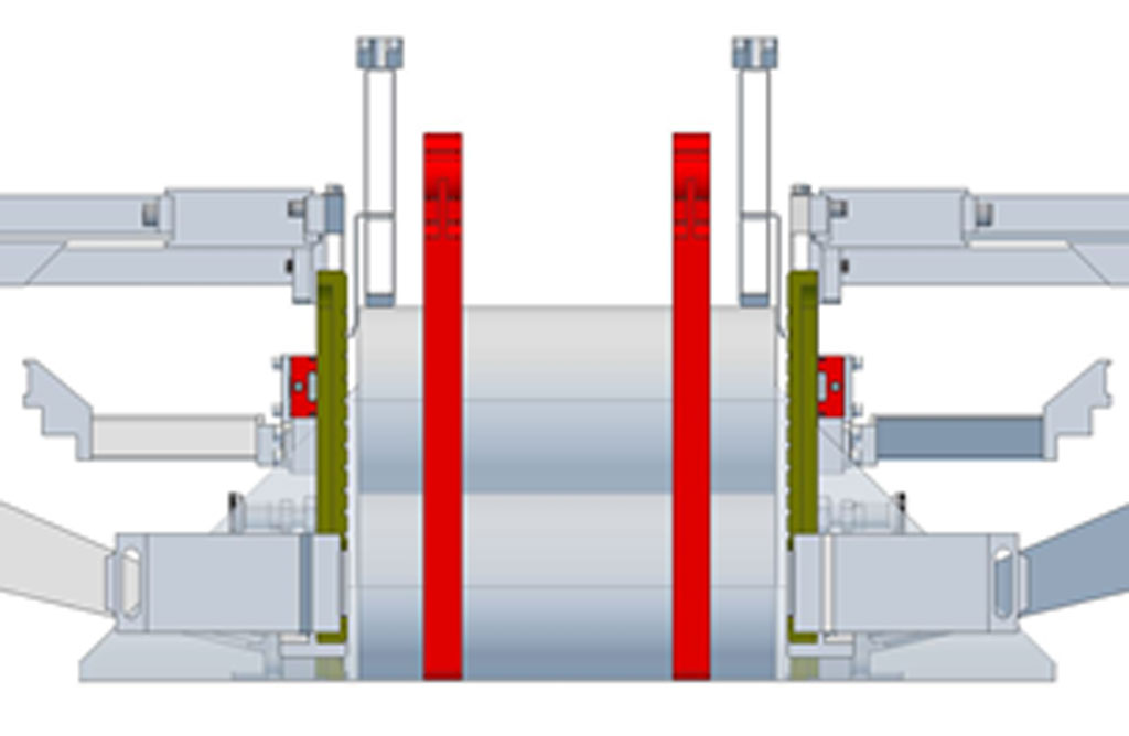
The following images pride examples of the setup of the contrast rails, and overhead fingers in relation to different package configurations
After the contrast rails have been positioned then the folders can be positioned. The faces of the head folders and counterfolders should either be in line or the head folders should be 1 to 2 mm closer to the package. Be sure to leave enough space so that the head folders does not rub against the folding bar.
Format BR221A

Format BR331A
Format KR412A
Format BR452A
Long packages will also require the use of offset brackets on the contrast rails. Without the offsets the contrast bars will not arrive to the edge of the package as needed. They will only be needed on the contrast rails on the head folder end of the machine, not at the sealing belt end of the machine
Offsets for CMW423, CMW424 and CMW425.
Offsets for MW42 and CMW42.
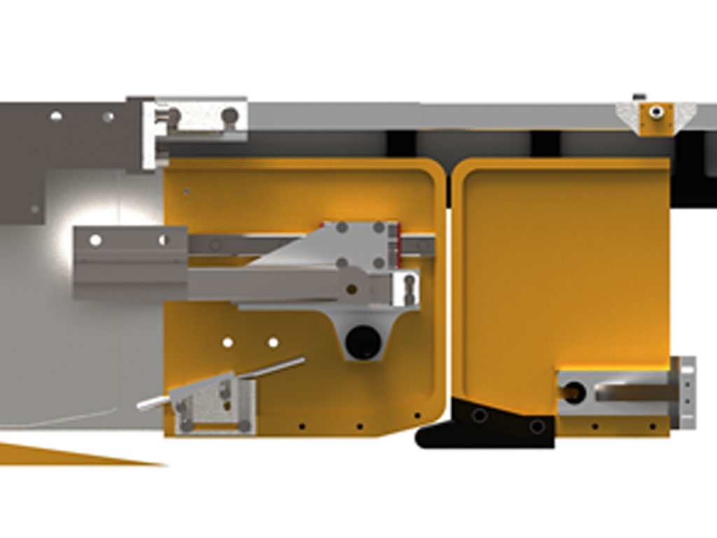
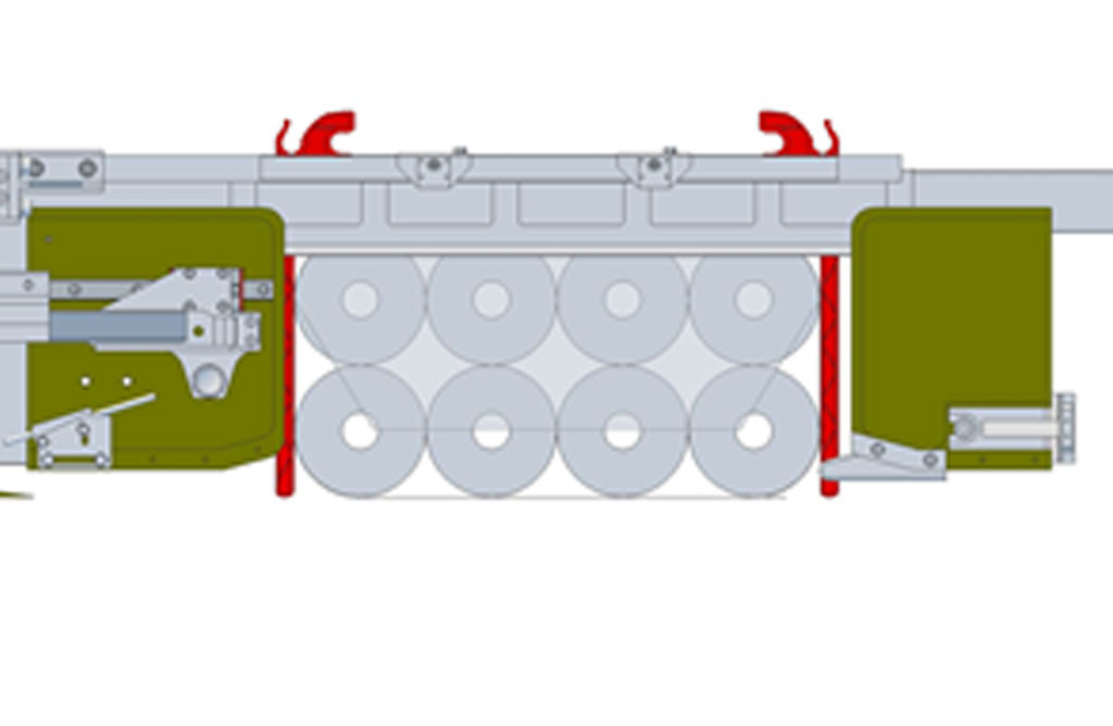
The following images are the same formats show in side view. The views show an approximate position of the machine components as the machine is jogged forward. The example positions are used for the positioning of the air jets. You see also demonstrated the 3 positions of the counterfolder corresponding to the three pitch configurations of the overhead.
Note: The timing of the lower folder, head folder and overhead fingers remains the same for the universal folders as for the conventional folders. The use of the Flaps Blow timing for the control of the air jets will require changing the timing on the Machine Phases page of the operator panel. The new phase will have an on phase of 25-30°. The following are approximate timings for air jets for different machine speed ranges
< 35ppm: On=0° - Off=25°
> 35ppm < 65ppm: On=350° - Off=15°
> 60ppm: On=340° - Off=5°
A two lane package will only require the use of one air jet. The 2nd air jet should be disabled.
A three lane package will only require the use of one air jet unless roll diameter is very large, eg. >135mm
Four lane packages will require the use of both air jets.
Also the use of the Fold Straightening blowers may be needed for larger, single layer packages. The timing will be dependent on the machine mechanical phasing but likely will be immediately after the stop position which is usually somewhere between 70° - 100°. Again a short phase is used, not more than 30°